From 2D to 3D in nuclear plant design – what India’s 700 MWe PHWR program taught the industry
The Kakrapar 700 MWe Pressurized Heavy Water Reactors (PHWRs) did more than raise India’s nuclear capacity. They changed the way Nuclear Power Corporation of India Limited (NPCIL) engineers design nuclear plants, shifting from 2D to 3D design.
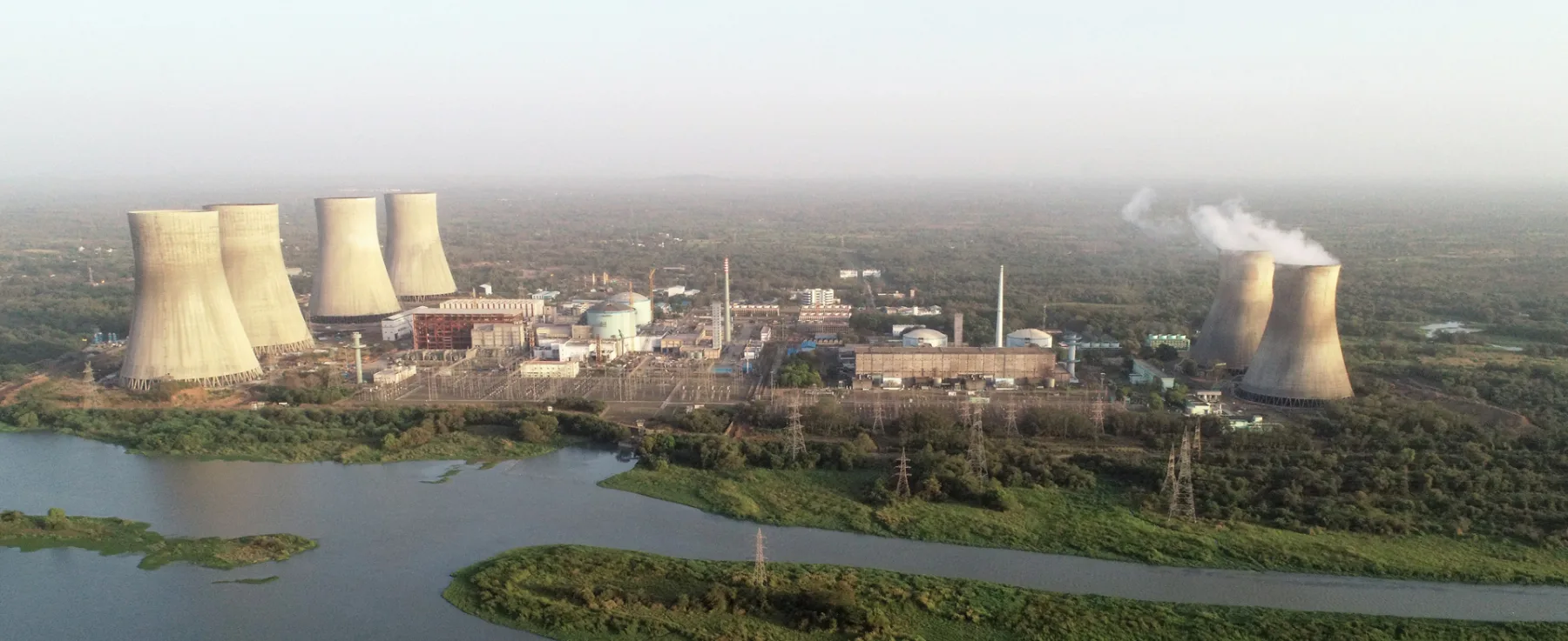
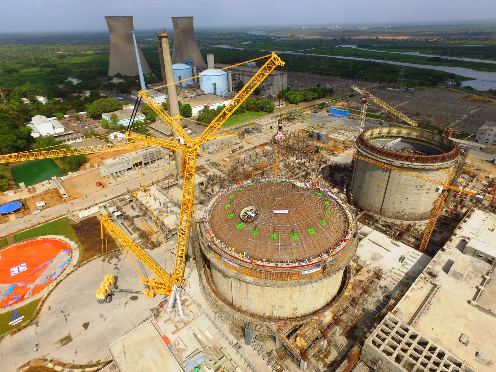
In July 2025, India’s Atomic Energy Regulatory Board granted NPCIL a 5-year operational license for India’s first 700 MWe PHWRs. Units 3 and 4 at the Kakrapar Atomic Power Station (KAPS) are the first 700 MWe PHWRs designed, built and commissioned entirely in India. They are also the first nuclear reactors designed in 3D at NPCIL.
KAPS 3 & 4 represent the beginning of a new era at NPCIL. In addition to the impressive capacity (700MWe), the “designed, built and commissioned in India” stamp marks possibly the most significant departure from past practices. Behind the scenes, another significant change took place: 3D model-based engineering was adopted to replace traditional 2D design methods.
Reaping the benefits of 3D design
In an article published in NPCIL’s Nu-Power magazine titled “3D Plant Engineering and Modelling of KAPS-3&4”, NPCIL Prasanta Kumar Pati, Dy. Chief Engineer, RDPS & UGP section and Sulok Kumar Saxena, Associate Director (Reactor Process Group), have highlighted the importance of the shift from 2D to 3D design on the projects.
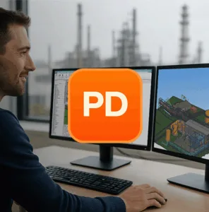
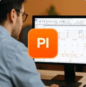
In the article, they describe their new model-based engineering workflow where the 3D model supports detailed design, multi-discipline checks, design reviews, and extraction of construction deliverables. The team selected Cadmatic as their plant modelling platform of choice (CADMATIC 3D Plant Design & CADMATIC P&ID) and used it through detailed engineering and coordination.
The table below summarizes the six main points the Nu-Power magazine article makes related to the challenges of 2D design and the advantages of 3D-model based engineering.
2D Challenge
- Detect clashes directly in the integrated model and resolve them early with multi-discipline visibility.
- Collision control tool used to identify interferences in the 3D model and resolve them via multidisciplinary review meetings; then validated in integrated walkthroughs.
- Quantities become model-derived, repeatable and consistent as design evolves.
- Accurate bill of quantities/materials extracted from the 3D model database (tabular quantities) and used to reconcile procurement after model completion.
- Model updates become the single source of truth deliverables regenerated from the same dataset.
- A defined set of deliverables were extracted from the 3D model (P&IDs, Concrete Forming Drawings, isometrics, GAs, etc.), reducing repetitive manual rework.
- Alternatives can be reviewed visually and spatially before committing to drawings.
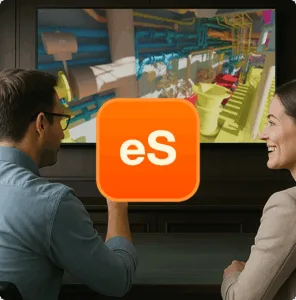
- Model exported to CADMATIC eBrowser for virtual walkthroughs; design deficiencies/ improvements identified by a walkthrough committee and implemented back into the model. eBrowser 3D model is useful for simulating approach paths, maneuvering time and radiation dose estimation and its minimization.
- Geometry-driven drawings reduce drafting mistakes, increase fidelity and improve consistency.
- The paper states extraction of accurate drawings from the 3D model and lists drawing types extracted for construction/erection use.
- 3D layout work is grounded in real elevations, access, removals, and reserve volumes.
- 3D modelling included a defined coordinate system and grids; modelling of openings/penetrations, cranes/hoists reserve volumes, platforms for O&M, and walkway/handling/ removal paths.
2D Challenge
- Detect clashes directly in the integrated model and resolve them early with multi-discipline visibility.
- Quantities become model-derived, repeatable and consistent as design evolves.
- Model updates become the single source of truth deliverables regenerated from the same dataset.
- Alternatives can be reviewed visually and spatially before committing to drawings.
- Geometry-driven drawings reduce drafting mistakes, increase fidelity and improve consistency.
- 3D layout work is grounded in real elevations, access, removals, and reserve volumes.
- Collision control tool used to identify interferences in the 3D model and resolve them via multidisciplinary review meetings; then validated in integrated walkthroughs.
- Accurate bill of quantities/materials extracted from the 3D model database (tabular quantities) and used to reconcile procurement after model completion.
- A defined set of deliverables were extracted from the 3D model (P&IDs, Concrete Forming Drawings, isometrics, GAs, etc.), reducing repetitive manual rework.
- Model exported to CADMATIC eBrowser for virtual walkthroughs; design deficiencies/ improvements identified by a walkthrough committee and implemented back into the model. eBrowser 3D model is useful for simulating approach paths, maneuvering time and radiation dose estimation and its minimization.
- The paper states extraction of accurate drawings from the 3D model and lists drawing types extracted for construction/erection use.
- 3D modelling included a defined coordinate system and grids; modelling of openings/penetrations, cranes/hoists reserve volumes, platforms for O&M, and walkway/handling/ removal paths.
Future nuclear expansion and NPCIL’s role
The KAPS 3&4 projects have paved the way for a fleet of ten more 700MWe PHWRs that will be built across India. As part of India’s ‘AtmaNirbhar Bharat’ (Self-Reliant India) initiative in advanced nuclear technology, they will reinforce the country’s clean, reliable baseload while reducing reliance on fossil fuels. It will also enable India to export its indigenous reactor technology and expertise to the world.
In this context, India’s Atomic Energy Act was recently amended in the form of the SHANTI Act to allow private entities to set up nuclear power plants. Apart from this, NPCIL has already launched joint ventures with NTPC (under the ASHVINI company name) and Indian Oil Corporation (NINECL).
NPCIL currently has 4 nuclear power projects under construction:
- Kaiga Atomic Power Project Units-5&6 (700 MWe PHWRs)
- Gorakhpur Haryana Anu Vidyut Pariyojna, Units-1&2 (2×700 MWe PHWRs)
- Kudankulam Nuclear Power Project Unit-3&4 (2×1000 MWe VVER)
- Kudankulam Nuclear Power Project Unit-5&6 (2×1000 MWe VVER)
In addition, the Government of India has granted administrative approval and financial sanction for ten 700 MWe PHWR units to be developed in fleet mode at four sites (including Kaiga-5&6) where pre-project activities are currently underway. (Source: www.npcil.nic.in)
Growing Cadmatic use
NPCIL has steadily increased its use of Cadmatic software over the years, initially ramping up for the design of units 3&4 on the Kakrapar Project where around 100 Cadmatic licenses were in use. Cadmatic is a proud partner of NPCIL in its quest to provide India with safe and reliable sources of energy for its growing economy.