Cadmatic P&ID: Intelligent drawings that connect to your 3D design
-
 Cadmatic P&ID
Overview
Cadmatic P&ID enables fast and accurate creation of process and instrumentation diagrams with unified data across your 3D models and electrical diagrams. Set design rules once and benefit from accurate data in a shared data environment. Less manual work and faster workflows for your project.
- Create intelligent, data-rich diagrams
- Maintain full design consistency with 3D models
- Customize library of standardized symbols to your project needs
- Reuse components across multiple projects
Benefits
-
Work faster with smart tools
Speed up diagram creation with intelligent symbols and auto-connect features. -
Link diagrams to 3D and Electrical
Ensure data consistency across all design stages with intelligent workflows. -
Minimize design errors
Built-in validation ensures consistency and accuracy at every step.
Features
-
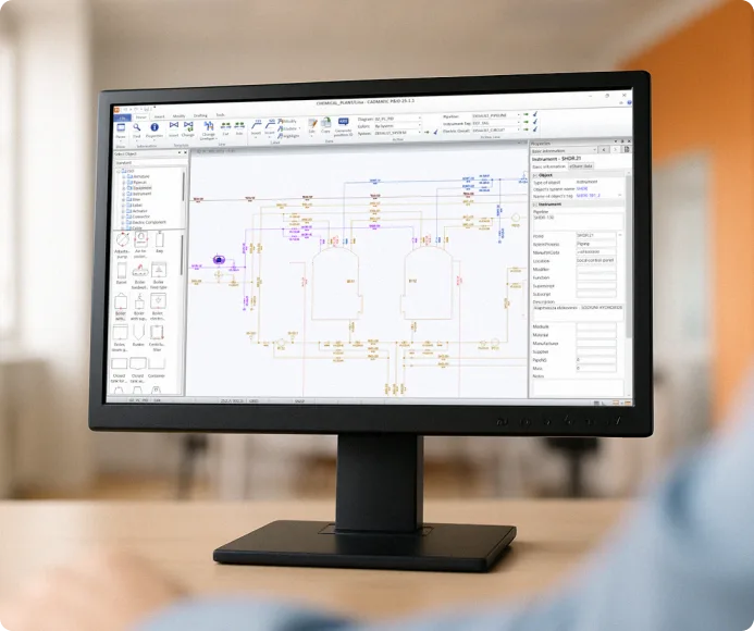
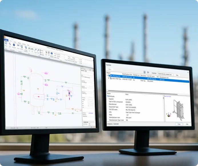
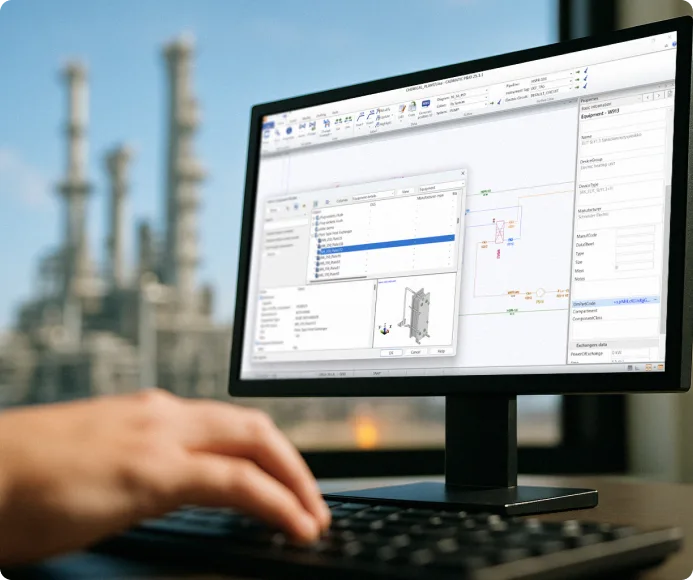
Intelligent P&ID diagram editor
Design P&IDs, PFDs, and schematic diagrams using data-rich symbols and connections. Symbols and connections automatically store and update object properties to ensure data consistency throughout the design process.- Auto-connect and drag features
- Symbol libraries with data rules
- Accurate data through consistency checks
-
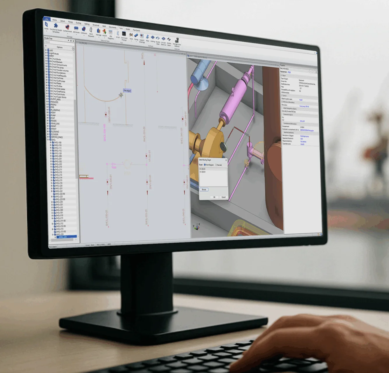
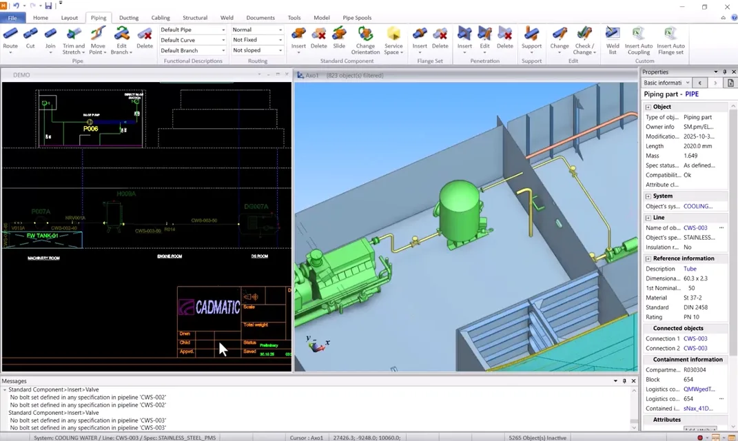
Built-in data connectivity to 3D
Connect your P&ID diagrams seamlessly to your 3D model. Cadmatic P&ID ensures full design traceability and error-free handover by maintaining consistent object IDs and bi-directional data flow between diagrams and 3D components.- Bi-directional data synchronization
- Unique object tagging supported with position ID generation
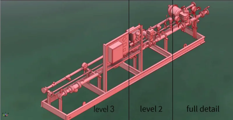
- Highlight 3D model progress in P&ID
- Data visualization with colors
-
Streamlined project setup and reuse
Standardize workflows with templates and projects defaults during setup. This way admins enable designers to work faster and with higher accuracy, as well as reuse the whole design diagrams, or any smaller units in processes.- Library-based design
- Admin-defined setup and customizable libraries
- Supports templates and standards such as ANSI/ASME, EN, DIN, and more
- Reuse across disciplines and projects

“The integration of 2D and 3D graphical elements with engineering data led to a drastic reduction in errors and the time required to generate lists.”


“The main reason we started using CADMATIC software was to reduce errors during the construction phase by designing with a common database. Using CADMATIC has had a positive effect on our working methods”
“The integration of 2D and 3D graphical elements with engineering data led to a drastic reduction in errors and the time required to generate lists.”
“The main reason we started using CADMATIC software was to reduce errors during the construction phase by designing with a common database. Using CADMATIC has had a positive effect on our working methods”
Frequently asked questions about P&ID diagram software
Can multiple designers work on the same project?
Yes. The multi-user environment allows several designers to work on the same model simultaneously, with real-time synchronization and change tracking.
What file formats are supported for export?
Cadmatic supports multiple industry-standard formats such as DXF, DWG, and STEP. You can also export to IFC and use integrations with PLM systems.
What is a P&ID drawing?
A P&ID drawing is a detailed process schematic showing piping, equipment, instrumentation, and control systems for an industrial process. It is created during the design phase and updated throughout a facility’s life as modifications are made.
How to make and read a P&ID diagram?
A P&ID diagram is drawn by placing process equipment symbols (vessels, pumps, heat exchangers), connecting them with piping lines, and adding instrumentation symbols and control loops according to your project’s symbol standards. In Cadmatic P&ID, you drag and drop intelligent components from a library, and the software manages the underlying data automatically. To read a P&ID diagram, start by familiarizing yourself with the symbol legend, then identify the main process equipment (vessels, pumps, reactors), follow the process flow lines between them, and note the instrumentation tags and control loops. The tag numbering system tells you the type and location of each instrument.
What is P&ID in engineering?
In engineering, P&ID stands for Piping and Instrumentation Diagram. It is a schematic that shows the interconnection of process equipment, piping, and instrumentation in an industrial plant. It is one of the primary design documents used across chemical, oil and gas, power, and pharmaceutical engineering.