Release Highlights 2025H1
Outfitting / 3D Plant Design
Automatic dimensioning
Dimension lines can now be automatically generated into Plant Modeller drawings. The dimensioning tool uses the reference lines grid to show the distance between a reference line and object’s centerline.
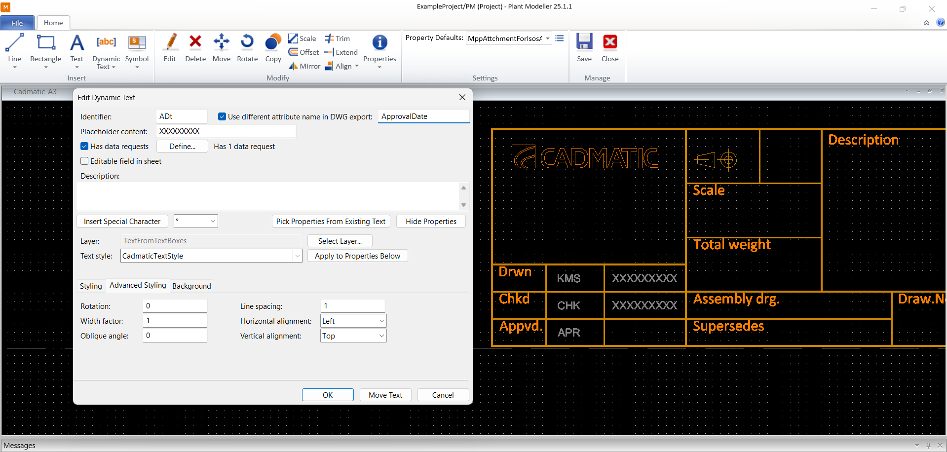
DWG drawing sheets
Plant Modeller documents can now use drawing sheets that utilize the DWG format. This especially improves how tables, block attributes, and pictures work.
Cable list pane
Cables can now also be managed through a dockable Plant Modeller pane. This allows many of the cable routing related actions to be performed without having to open the Cable Router tool.

More 3D import and export formats
Component Manager and Plant Modeller are now able to import many additional 3D file formats, such as SAT, Parasolid, CATIA V5, SolidWorks, Inventor, and Solid Edge. Moreover, the STEP format can now also be exported.
ROHR2 integration
We are pleased to announce an update to our PCF system, which now includes a comprehensive set of fixed pipeline attributes for seamless integration with Cadmatic. When a Cadmatic pipeline attribute description matches a fixed PCF keyword, the attribute is automatically written into the PCF file in PCF export.
Key features:
- Automatic attribute matching: Attributes such as operating pressure and temperature are automatically recognized and added to the PCF file using fixed keywords like ‘PIPELINE-TEMP’ and ‘OPERATING-PRESSURE’.
- Extensive keyword list: The update includes a detailed list of fixed keywords for various pipeline attributes, ensuring thorough and accurate data integration.
Fixed keywords:
PAINTING-SPEC, MISC-SPEC1, MISC-SPEC2, MISC-SPEC3, MISC-SPEC4, MISC-SPEC5, JACKET-SPEC, REVISION, AREA, DATE-DMY, NOMINAL-CLASS, NOMINAL-RATING, BEND-RADIUS, PIPELINE-TEMP, PIPELINE-TYPE, SPECIFIC-GRAVITY, SPOOL-PREFIX, CLEANING-REQUIREMENT, PAINT-COLOUR, CONSTRUCTION-TYPE, DESIGN-PRESSURE, DESIGN-TEMPERATURE, ENGINEERING-WORKPACKAGE, INSTALLATION-WORKPACKAGE, FLUID-CODE, HANDOVER-SYSTEM-ID, TRACING-REQUIREMENT, TEST-PRESSURE, MAIN-NS, OPERATING-PRESSURE, PID-DRAWING-NUMBER, ALT-DESIGN-PRESSURE, ALT-DESIGN-TEMPERATURE, DESIGN-CODE, FLUID-PHASE, FROM, HANDOVER-SUBSYSTEM-ID, INSULATION-SPEC-NUMBER, NDT-REQUIREMENT, PID-REVISION, PROCUREMENT-WORKPACKAGE, STRESS-CATEGORY, STRESS-PACKAGE, TEST-MEDIUM, TO, PWHT-REQUIREMENT, SEQUENCE-NUMBER, CONSTRUCTION-WORKPACKAGE, MATERIAL-OF-CONSTRUCTION.
This update aims to enhance the efficiency and accuracy of attribute integration in the PCF system, providing a more streamlined and user-friendly experience.
P&ID
System and line management
There is a completely revised tool for managing the systems and lines of the design project in both P&ID and Plant Modeller. This tool lists all the systems and lines as a hierarchical view. The properties of the systems and lines can easily be reordered and filtered, and they can be edited within the tool as well as exported and imported in Microsoft Excel format.
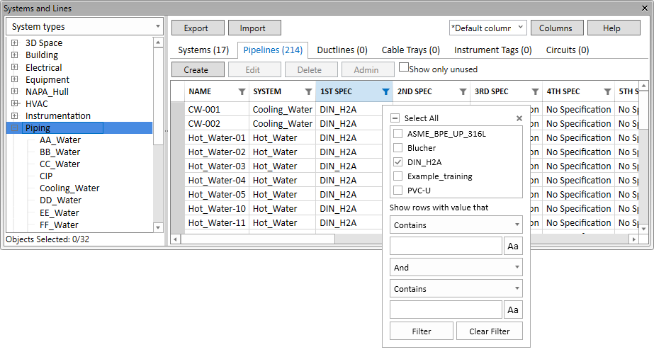
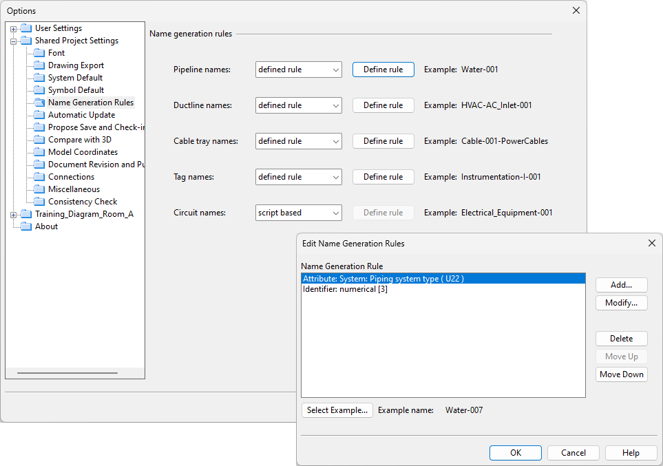
When creating new lines, the default names are now generated with naming rules defined by the project administrator.
2D symbols for nozzles and actuators
The connection node properties of specific diagram symbols now allow the designer to select a custom 2D symbol to be displayed at the node’s position. This feature allows for providing a graphic representation for the nozzle of a tank or the actuator of a valve. The node editor also shows if equipment nodes are mapped to a GDL node, and the size is then inherited from the GDL automatically.

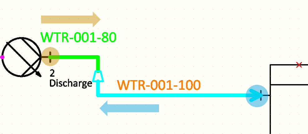
Nominal size propagation to pipelines
The nominal size value of a specified connection node can now be propagated to the other connection nodes along the pipe run. Components like reducers that may have more than one NS size defined are automatically reversed if the propagation causes the previously smaller size to become the bigger size (or vice versa).
Web API
Improvements to the Web API
- The Web API now supports dynamic model queries. 3D exports can define the model query as part of the request, instead of having to define the query in advance in COS.
- The Web API now has endpoints for integrating cable design with CADMATIC Electrical or other electrical software. These endpoints can read and write cable data by utilizing external objects.
Hull
Improved handling of split plates
The enhanced method for handling complex plates which was introduced in the 2024T3 Jumbo Panels Beta Version is now included in the 2025H1 release.
Plates split by soft seams, holes, or splitters are treated so that each plate part has its own logistical record, including individual thickness and material type. This simplifies the design of large structures with varying properties and saves time in both modeling and production planning.
Note that when a project is opened in 2025H1 for the first time, it is converted to be compatible with the new plate functionality. The project conversion cannot be reversed, and after the conversion the project cannot be opened with an earlier version.
PDF instructions from WBD stages
It is now possible to automatically generate PDF documents which contain images of the building stages according to the work breakdown structure with the new Generate PDF feature in Hull Viewer.
The generated PDF documents show the building stages by WBD blocks. Different layouts can be defined for the pages: one for the first page, one for overview pages, and one for regular pages which contain the images.
It is an easy way to produce clear, realistic instructions that support better communication and smoother assembly.

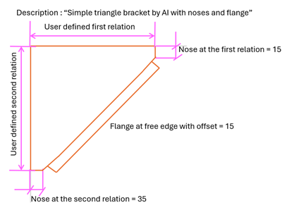
AI-generated bracket type files
Text input can be used to predefine complex bracket geometries with Cadmatic AI. You can create, edit, and interpret bracket type files using simple text prompts.
It is a faster, smarter way to define, update and re-use bracket-type files in the project norms. This feature reduces manual work and improves detailing efficiency.
Information Management
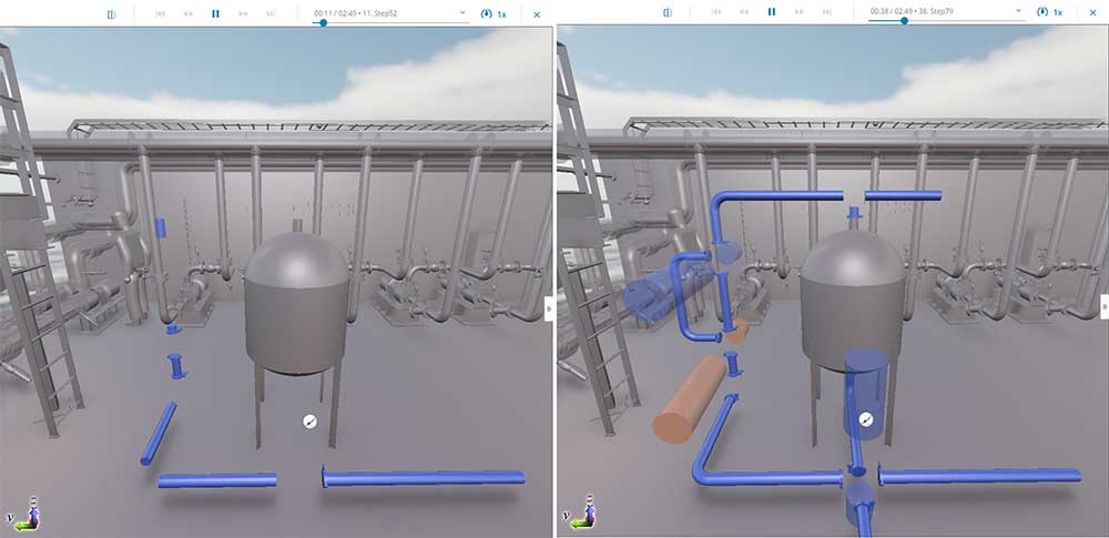
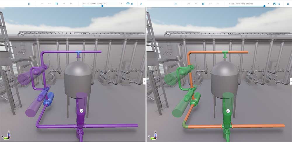
4D Sequencing in eShare App
4D sequencing enables visualizing object status changes in the model within a defined time period. This dynamic sequence can be shown as a smooth animation in eShare App. Creating the animation only requires configuring either a 4D sequence data source for database adapter or utilizing status trackings as the data source. By visualizing each stage of the process, teams can effortlessly monitor progress, ensure alignment, and drive the project forward efficiently.
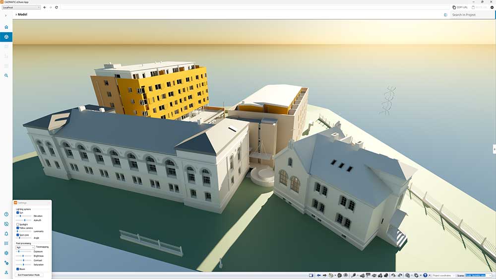
Presentation Mode (beta) in eShare App
Presentation mode offers a significantly enhanced experience of viewing your 3D models in an entirely new light in eShare App. Powered by an advanced rendering technology called ray tracing, presentation mode delivers scenes with realistic and physically accurate lighting. The visualization mode incorporates modeling different material types together with light interaction, which can be selected from different sources including sun, sky, and spotlight, creating visually compelling presentations.
There are numerous options available for customizing the look, from sun positioning and spotlight behavior, to tonemapping, exposure, brightness, contrast, and saturation. These settings help ensure the model is presented in the best way possible.

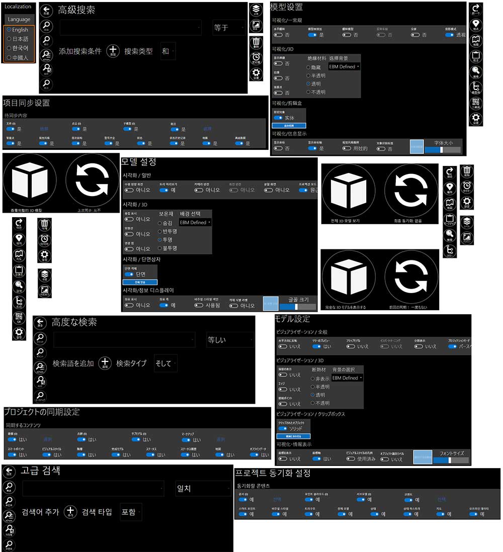
Localization in eGo
eGo is now available with user interfaces localized in Japanese, Korean, and Simplified Chinese. This expanded localization support empowers global teams to work more efficiently and intuitively by accessing project data in their native language. Whether collaborating across borders or supporting regional offices, teams benefit from a smoother, more inclusive user experience. The interface language can be easily changed in the settings menu or selected during installation.
Electrical
SQLite to replace Access databases
The new support for SQLite as a local database format brings a significant performance boost compared to Microsoft Access. In addition, users no longer need to worry about unexpected updates.
A few things to consider:
- When creating a new project with 2025H1, the database format will be SQLite.
- If users want to continue with old projects (2024T3 or older) after taking 2025H1 into use, the databases can be converted to SQLite. Alternatively, users can continue with the existing Access project databases.
- If users decide to use the new database format, it cannot be converted back to Access.
- It is good to make sure there are backup files before conversion.
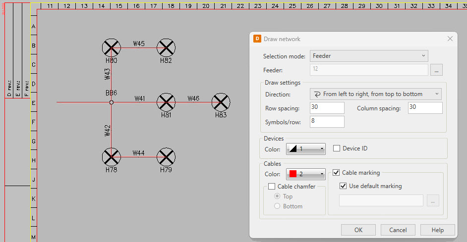
Group/feeder number and feeding distribution board for connected devices, cables and distribution boards
Our electrical network has taken serious steps forward. Now, the network is more intelligent, allowing users to easily check from any device which distribution boards and feeders they are connected to.

Networks can be defined as actual cable connections in the drawings or alternatively in the DB tool. When the network is complete, automated functions based on drawings, devices or feeders can be used to customize the network appearance in several ways.
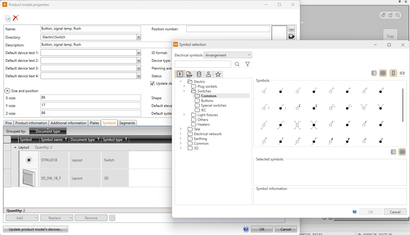
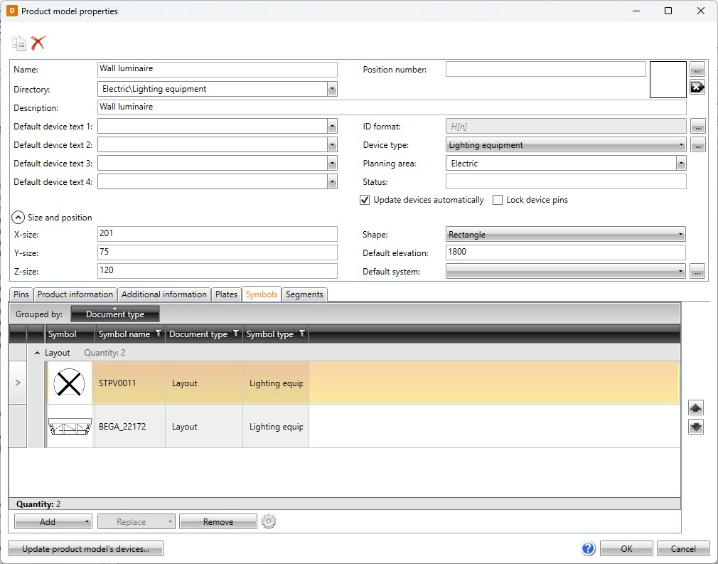
Product model renewal and symbol selection
The product model properties dialog has been modified to look similar with the likes of device and distribution board properties. This renewal makes all dialogs more unified, making them easier to learn and use.
In addition to the product model property dialog, symbol selection has been renewed – instead of the icon menus, symbols are now selected in a separate dialog in all functions. The same dialog is available in the DB tool, making it now possible to select symbols there as well. Furthermore, user symbols are now available both in the new symbol selection as well as in the Symbols window which is otherwise already familiar from the previous releases.
All in all, it is now a lot easier to find the desired symbols in device and product model properties, for example.
Additional project languages
New design languages have been added into the project settings. You can select your project language from the broad language list to change your project’s wiring color abbreviations, default frame, and symbol description, for example.
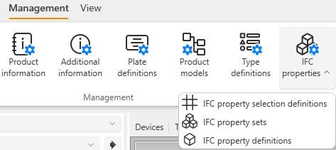
IFC property sets
Property sets and properties are now in the database. You can define the properties in the database and add definitions to your property sets, after which you can create selection definitions to be used when exporting IFC files from Electrical. Selection definitions can include as many property definitions as needed. This is a fundamental change in managing property sets – this way, the changes will be easily available to all project members.
Another change related to IFC properties is that they can now be defined based on device types (instead of IFC types).
Type definition
Different devices and locations require different type definitions depending on the locale and project. Even when designing using the same locale, there are different types of projects. Therefore, users are now allowed to create their own type definitions for devices, locations, cables, and cableway systems. Settings for the desired IFC type are also included.
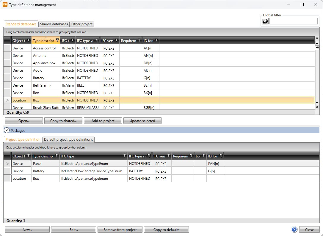
Definition of default ID format
Do you have any preferences regarding how the IDs should be structured when creating devices? Now you can define how to form the default IDs. As mentioned above, users can create their own device types – this feature enables project-specific rules on how to form the IDs for these device types.
DIALux import improvements
The previous release introduced the DIALux import that allows users to import luminaires to their correct places and with all the selected product information. Now, the import has been improved even more by allowing users to import luminaires with 3D features. These 3D symbols can be used in upcoming projects, since they are saved into the project directory.
Integrations: Cableway export from Electrical to Cable router
Users can carry out the basic design in Electrical, including cable tray design (in 3D format). When the time for detailed designing comes, the cable trays can be transferred to CADMATIC Plant/Outfitting using an MDL transfer file. The transfer file contains all the necessary information for importing the cable trays and using them to route cables as if they were originally designed in CADMATIC Plant/Outfitting.
Draw
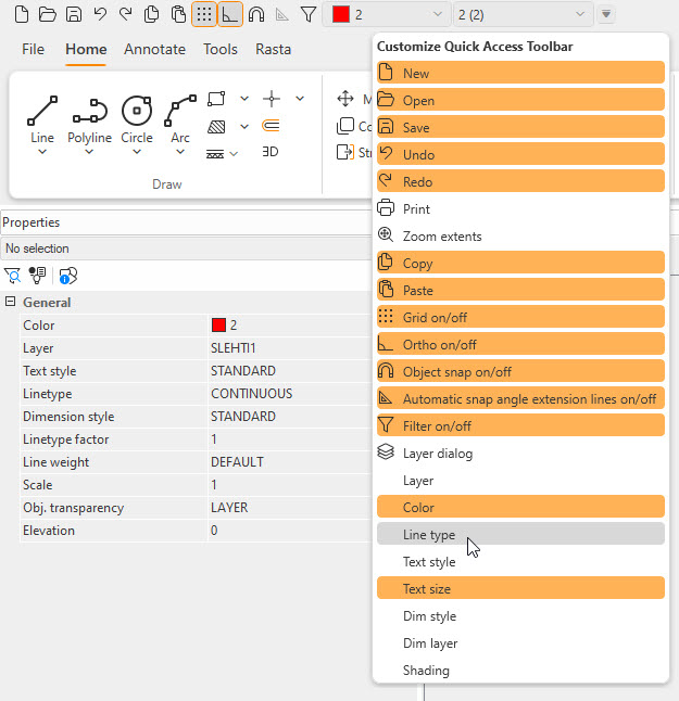
Smarter and smoother Draw experience
In CADMATIC Draw 2025H1, the usability has been improved by adding new functions to the quick toolbar to facilitate, for example, the change of color and layer. The user can choose the functions displayed on the quick toolbar.
IFC functions have been significantly developed by adding support for IFC versions 4.0.2.1 and 4.3.2.0, in addition to which performance has been improved. Thanks to these performance improvements, IFC models can take up to 50% less memory compared to before.
In annotation functions, it is now possible to use a symbol as a reference object marking element instead of text. This enables the creation of more diverse annotations.
Printing to a PDF document is now possible without a printer driver installed on Windows.